FEA is a powerful tool for engineers to simulate real-world problems and understand the behaviour of complex structures. It is important to prepare each FEA simulation properly before running it.
From my experience, the most important step in FEA is to define and understand your engineering problem. You need to establish a goal for your simulation and clear questions to answer.
FEA software can be an expensive investment for engineering companies. However, if used correctly, it can save thousands of dollars by getting products right-first-time, without manufacturing multiple prototypes.
It can help us predict how a part, or design, will behave in the real world by simulating it in a virtual environment.
In this article. I will outline a simple FEA example, explaining the most common steps that can you can apply to all FEA simulations, regardless of the engineering design or problem.
You should follow the following steps when preparing and running an FEA problem:
1. Define The Problem
The first step when running an FEA problem is to define and understand the engineering problem. Establishing a goal for the simulation and understanding what questions you need to answer will help ensure you get the results you need from your simulation. It’s important to consider what physical phenomena are likely to play a role in the design and determine which assumptions need to be made in order to simplify the model.
At this stage, I like to plan my simulation and think through the steps, so I ensure I have everything I need to perform an accurate simulation and have a full grasp of what needs to be simulated.
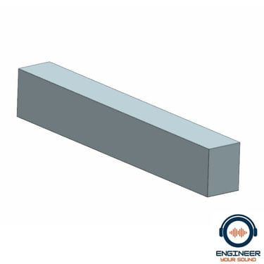
In the following example, we have a simple beam that is clamped on one end. Our aim is to work out if this steel beam can withstand a force of 100N placed on one end without breaking.
2. Establish A Clear Goal
Establishing a clear goal is essential for any FEA problem. A good practice is to write down the result you are looking for and the parameters you will use to measure success. This will help ensure that your simulation is focused on achieving the desired results.
It is important to clearly define the questions you need to answer through the simulation. For example, will this product pass a drop test from a height of 1m?
If you do not clearly establish the questions you want to be answered from an FEA simulation, you may miss important data or waste time concentrating on aspects of the simulation or model that are not relevant.
In our example, we have a clear question to answer; “will this steel beam break when a downward force of 100N is applied to the end?”
3. Refine & Clean The CAD Geometry
Refining and cleaning up the CAD geometry is an important step in any FEA simulation. All CAD objects should be checked for tolerance errors, gaps and overlaps before being exported to the FEA software. It is important to check all edges, faces and surfaces of the model for any imperfections that could affect the accuracy of the simulation.
In addition, to reduce the number of elements and improve speeds, it’s good to remove any unnecessary features from a CAD model, for example, tiny radii.
When optimising the geometry for an efficient mesh, it is important to only remove or clean features that you are confident are not required for the performance of the model.
In this example, there are tiny radii in the corners of the beam. From experience, we can conclude that these tiny radii can be removed as they are so small, the corners of the beam act as if they are not there in reality.

4. Mesh The Model
Mesh generation is an important step in FEA simulations, but it can be time-consuming and difficult to get right.
If the mesh isn’t accurate enough, or too dense, then the simulation results will not be reliable. This can lead to wasted time and resources as well as incorrect product designs that don’t perform as expected in real-life applications.
To ensure accurate results from your FEA simulation, you need a good-quality mesh. With modern FEA software, this process has become easier with automated meshing tools that generate high-quality meshes quickly and efficiently. By using these tools, you can save time and money while ensuring your simulations are reliable and accurate every time.
Many novice simulation engineers will apply a tet mesh to geometry and not spend time refining or ensuring that the mesh is suitable to capture the design intent.
Although tet meshes are fast and very effective, more experienced engineers can manually mesh components and designs. This has the added benefit of ensuring that the simulation size is not too large and that the element size is suited for describing the geometry and model.
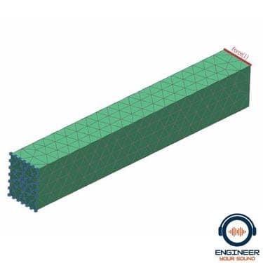
In the following example, we have applied a generic tet mesh to the beam. However, I suggest you use a hex element mesh for such simple geometry.
6. Apply Boundary Conditions & Loads
Once you have applied a mesh to your model, applying boundary conditions is an important step in getting accurate results. Boundary conditions are used to define how forces and displacements will be applied to the model. This is critical to ensuring realistic simulation results.
The most common type of boundary condition used in FEA analysis is a displacement constraint, which defines how a component can move. For example, in a drop test simulation, we might constrain the bottom face of the model so that it simulates an impact on a solid surface.
It is important to ensure you correctly apply boundary conditions, as this will affect how accurately your simulation results match reality.
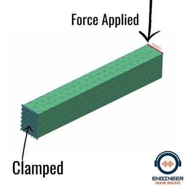
In the following example, the beam is clamped on one end and a load is applied to the other. These are simple boundary and load conditions. No other forces are acting on this part.
7. Define Material Properties
Defining material properties is a critical step in completing an FEA simulation. This involves specifying the properties of your materials, such as their strength and flexibility, which will affect how they behave in the simulation.
When defining material properties, it is important to ensure that you have realistic values that accurately reflect the properties of the material in real life. If you don’t have accurate values, then your simulation results may not be reliable.
In this example, we know exactly what grade of steel we are using and can therefore confidently apply the material properties with the correct material mass density; Young’s Modulus and Poisson’s ratio.
8. Run The Simulation
Once you have completed all steps above, you are ready to run the FEA simulation. Depending on the complexity of your model, this can take anywhere from a few minutes to a few hours or even days. Once the simulation is complete, you can view the results and make changes if necessary.
9. Mesh Convergence Checking
Mesh convergence check is an important part of any finite element analysis (FEA) simulation. It is a process that ensures the mesh used in a model is accurate and suitable for capturing the design intent. In FEA, mesh convergence checking involves running simulations with different mesh densities to determine if any further refinement of the mesh is necessary for reliable results.
You should complete the mesh convergence check after you have applied all boundary conditions and loads to the model. The goal is to determine the optimal mesh density that will yield the most accurate results without taking too long to run or increasing simulation costs.
In reality, you want a mesh size that is small enough to fully capture the geometry but not one that is so small it will create overly long solve times.
10. Interpreting The Results
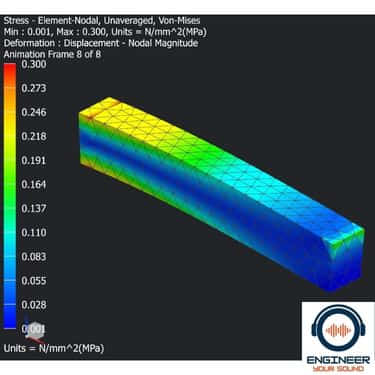
The last step in completing your FEA simulation is to interpret the results. This involves looking at the outputs from the simulation and seeing how they match up with reality. You might also look for specific data, such as stress levels, displacement values or even frequency and modal analysis.
Once you have studied the results, it is important to make any necessary changes to improve the design before running another simulation. You can repeat this process until you are confident that your simulation results match reality as closely as possible.
I have found that it is very important to discuss your results with fellow engineers. This can open your mind to any aspects of the simulation you may have missed or should further define.
In addition, your simulation results should stand up to questioning and peer review by your fellow engineers.
11. Verify The Results
Once the simulation is complete and the results have been interpreted, it is important to verify the accuracy of the results.
This involves conducting tests, such as validating against real-world test data or experimental data.
Modern FEA software can provide fancy graphs and pretty pictures that can convince us we know what we are doing. However, without real-world testing and verification, our simulations could be nonsense.
We need to verify that the results we have attained are equivalent to what we see in reality.
Final Thoughts
In conclusion, running an FEA simulation can be a complex process that requires careful planning to ensure accurate results.
It is important to check all edges, faces and surfaces of the model for any imperfections that could affect accuracy.
Optimising geometry and selecting suitable materials are also essential steps in getting reliable results from your simulations.
You must not overlook mesh refinement, as it plays a pivotal role in ensuring the mesh accurately captures design intent.
Finally, you need to apply boundary conditions correctly, so that forces and displacements are defined properly within the model before you run your simulation.
Regardless of your simulation problem, when you have completed these steps successfully, you have a higher probability of getting accurate results from your FEA analysis.