Modal analysis is a fundamental tool for simulation engineers, particularly if you work with components that are subjected to vibration.
Modal analysis is one of the most common forms of FEA (finite element analysis) and is used to show us the natural frequencies of a system and corresponding mode shapes.
To interpret a modal analysis result, step through the natural frequencies of the component and observe the mode shapes. You should check if your component has a natural frequency within the operating frequency of your larger system.
For example, let’s assume that you have a mechanical system which gets subjected to frequencies in the 20Hz to 200Hz range. If you have a component with a strong resonance (first mode) in this frequency range, it could vibrate and fatigue if it resonates, resulting in system failure.
Modal analysis is a fantastic and simple tool to identify the resonant frequencies of components and predict how they will respond to vibration.
In this article I will cover:
- What is a modal analysis?
- How does a modal analysis work?
- How do you interpret modal analysis results?
- What is a resonant frequency?
- Does modal analysis have units?
- How many modes should I solve for?
- What is a modal analysis used for?
- Is a modal and natural frequency analysis the same thing?
- Should I apply a load in a modal analysis?
- Should I apply constraints in a modal analysis?
What Is A Modal Analysis?
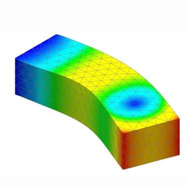
A modal analysis is a form of finite element analysis that allows us to examine the natural frequencies and mode shapes of a structure or component.
In simple terms, with a modal analysis, you are evaluating the distinctive deformation shapes that the structure or component will assume at each of its preferred oscillating frequencies. [source]
How Does A Modal Analysis Work?
Like all FEA (Finite Element Analysis), there is complex mathematics to describe the numerical solution.
In the interest of keeping to the fundamentals, you can describe modal analysis as the most fundamental of the dynamic analysis types, which looks for the natural frequencies of a structure.
All structures and components have natural frequencies and it is essential to understand these natural frequencies so we can try to predict how a structure or component will behave when exposed to vibrational frequencies in the field.
Typically, a component or structure is constrained and when a modal analysis is executed, it will extract the frequencies at which the component or structure will naturally resonate.
By knowing these resonance frequencies of a structure or component, we can design our parts to ensure that these resonant frequencies are outside the range of operation for our application.
For example, imagine you have a lawnmower engine that vibrates in the frequency range between 100Hz-350Hz. If you have a metal bracket that has a resonant frequency in this range that is part of the engine, it could oscillate too much, fatigue and fail.
If you would like to read more about the mathematics that describes a modal analysis, I recommend the book “Building Better Products with FEA” by Vince Adams and Abraham Askenazi,
How Do You Interpret Modal Analysis Results?
Typically, when you run a modal analysis, you will be presented with a solution where your model is suspended in free space, with a list of modal frequencies.
By stepping through the frequencies, you will see the natural frequencies of the component and the corresponding mode shapes.
Does A Modal Analysis Have Units?
A very common mistake when interpreting modal analysis results is to assume that the displacement of the deformation shown correlates to actual distance. This is not the case.
A modal analysis does not have units. A modal analysis will not tell you how much a component will deform in terms of distance.
A model analysis will only tell you:
- The natural frequencies of a component
- The mode shapes
In addition, with a modal analysis, a safety factor result or stress results will not be present.
Most FEA software gives the mode shapes in displacement, which could be specified in meters or inches depending on where you are in the world.
For many, this is very confusing, as it is easy to assume that the deformation result corresponds to actual distance measurement, but this is a false assumption.
In reality, the deformation distance has no real meaning. The resultant deformation that you may observe is the deformation shapes (mode shapes) that the component will experience at each of its natural oscillating frequencies.
It will not give you the real displacement of the mode shapes.
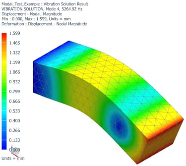
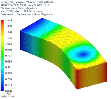
Below is an example of a very simple aluminium beam, constrained at one end.
The simulation software has given me the first 5 modes of this structure.
Below is an image of the first mode, or natural frequency, that occurs at 1043.24Hz. As you can see from the colour map, the result is showing me the intensity of deformation at this frequency.
Mode 1 – Frequency 1043.24Hz
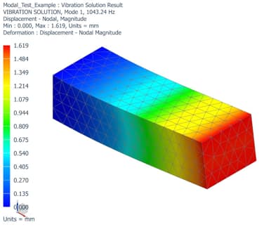
Mode 2 – Frequency 1322.34Hz
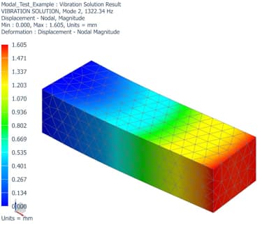
Mode 3 – Frequency 3666.49Hz
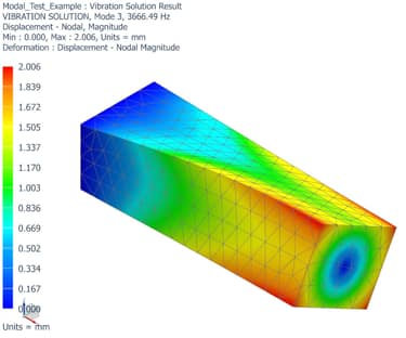
Mode 4 – Frequency 5364.92Hz
Mode 5 – Frequency 6062.13Hz
What Is Resonant Frequency?
The resonant frequency of a structure is the frequency at which the structure will vibrate with the highest amplitude. [source]
It’s fair to say that most systems will have a resonant frequency, which is usually called the first mode or fundamental frequency, where the amplitude will be the highest. [source]
This does not mean that we ignore higher modes or frequencies, however, as it depends on your application and how frequencies impact operation.
We usually denote the resonant frequency as “f0”. [source]
How Many Modes Should I Solve For?
In a modal simulation, the number of modes is technically infinite.
Each simulation software should give you the option to solve for several modes. For example, you may just specify that you want to look at the first 10 modes of a simulation.
You must be careful to ensure that you have selected enough modes to cover the frequency response of interest. It could be detrimental to only solve for the first 10 modes, but then realise that your simulation has problematic modes at a higher frequency.
Because you just solved for the first 10 modes, you may not have hit the frequency of interest.
Working with audio and speaker design, typically our components operate in the 20Hz to 20kHz region. Therefore, when completing a modal analysis of a component in a speaker system, you can solve your solution to check all the modes in this frequency band.
What Is A Modal Analysis Used For?
We use modal analysis for applications where a system is subjected to vibrations or accelerations and the effects of these vibrations must be studied.
Some practical examples of modal analysis applications in the real world include:
- Studying vehicle noise
- The vibration of a car body
- The vibration of an aeroplane wing
- The vibration of a wind turbine propeller
- Noise vibrations excited by a loudspeaker
- Bridge design
- The building design for earthquakes
Is A Modal And Natural Frequency Analysis The Same Thing?
Modal frequency analysis and natural frequency analysis are the same thing.
It can be very confusing when working with modal analysis, as terms can get used interchangeably. Modal analysis and natural frequency analysis is an example of two terms that often get used interchangeably but mean the same thing.
We can also refer to modal analysis as a normal mode or eigenvalue analysis.
Should I Apply A Load In A Modal Analysis?
You should not apply a load in modal analysis.
Modal analysis does not show us the response to loading.
If you would like to apply a load, then you will perform a frequency response dynamic analysis if your input is a frequency or a time response dynamic analysis. (Also known as a transient response analysis)
Should I Apply Constraints In A Modal Analysis?
Whether you should apply constraints in your modal analysis will depend on the application.
It is unnecessary to apply constraints in modal analysis, as the component or structure can be analysed without constraints, which will give you the free-body modes.
Many analysts seem to disagree or debate whether constraints should be applied, as all simulation problems are different.
Personally, I think that introducing constraints is important as you will get different results for models with and without constraints.
When working on real-world problems, I want my simulation to represent what is happening in reality. Therefore, I try to constrain my model and create a simulation which accurately represents how my model is constrained in the real world.
Adding constraints introduces stiffness, and I have found that if I try to optimise my model without constraints, I can spend a long time trying to optimise a non-accurate model, i.e. my model without constraints is not representative of the real-world application.
Final Thoughts
Modal analysis is a process of solving for the natural frequencies and mode shapes of a structure or component.
By understanding the natural frequencies and mode shapes, we can better understand how the system will respond to vibrations or accelerations.
This is fundamental to ensure that the resonant frequency of our system or part is not excited to the extent that it can cause failure.
